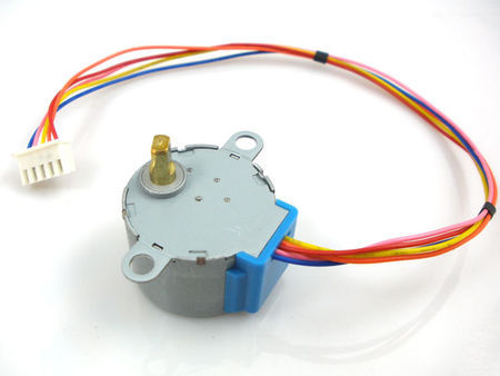
Stepper Motor is a motor controlled by a series of electromagnetic coils. The center shaft has a series of magnets mounted on it, and the coils surrounding the shaft are alternately given current or not, creating magnetic fields which repulse or attract the magnets on the shaft, causing the motor to rotate.
This design allows for very precious control of the motor,There are two basic types of stepper motors, unipolar steppers and bipolar steppers .
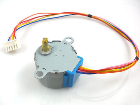
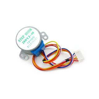
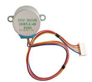
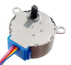
In This instructable , I will talk about an Unipolar Stepper Motor 28-BYJ48 .
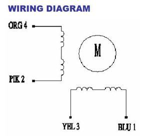
The unipolar stepper motor has five or six wires and four coils (actually two coils divided by center connections on each coil). The center connections of the coils are tied together and used as the power connection. They are called unipolar steppers because power always comes in on this one pole.
Step 1: Specification , Motor Driver
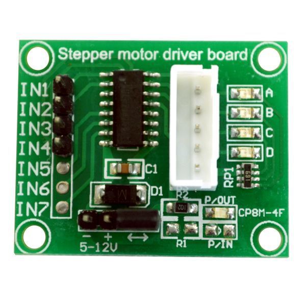
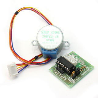
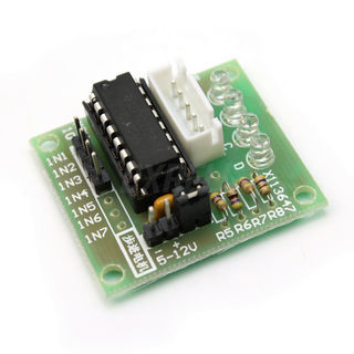
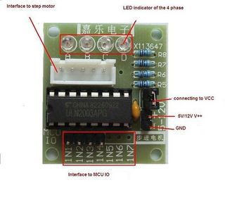
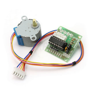
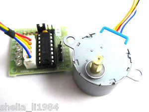
The 28-BYJ48 Even comes with Breakout using ULN2003 As a Motor driver chip .
Specification for this Motor ” And you can download datasheet from the attachment “Rated voltage : 5VDC
Number of Phase 4
Speed Variation Ratio 1/64
Stride Angle 5.625° /64
Frequency 100Hz
DC resistance 50Ω±7%(25℃)
Idle In-traction Frequency > 600Hz
Idle Out-traction Frequency > 1000Hz
In-traction Torque >34.3mN.m(120Hz)
Self-positioning Torque >34.3mN.m
Friction torque 600-1200 gf.cm
Pull in torque 300 gf.cm
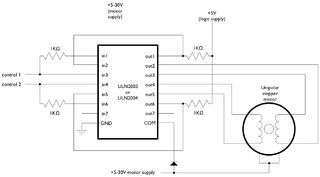
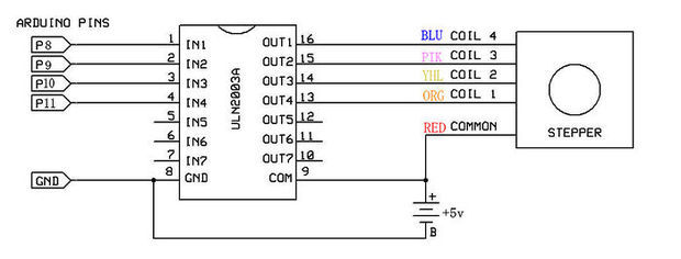
Insulation grade Aand the schematics of This breakout shown like the Pictures on the attachment
Note that if you want to use L293 Instead of ULN2003 , You will need to leave Red wire No connection.
Materials :
you will need :
1) Arduino Board .
2) BYJ48 Stepper Motor 5v
3) ULN2003 Moror driver Module
4) Jumper .
5) 5v voltage source “Optional” .
Step 2: Arduino Code .
 \
\The Arduino IDE Support a Library for Stepper Motor , Very Easy to use , After Connect Motor with arduino You can Upload the Sketch on to the arduino .
But …
You must take something in consider :
This Motor has a Gear ratio of 64 , and Stride Angle 5.625° so this motor has a 4096 Steps .
steps = Number of steps in One Revolution * Gear ratio .
steps= (360°/5.625°)*64″Gear ratio” = 64 * 64 =4096 . this value will substitute it on The arduino Sketch
For adafruit Stepper Motor , the Stride Angle 7.5° and Gear ratio is 16 , So number of steps in 1 Revolution is :
steps in One Revolution = 360 / 7.5 = 48 .
steps= 48 * 16 = 768
That’s will be different depend on what motor you are using , So check The Datasheet for Your stepper Motor to calibrate this values
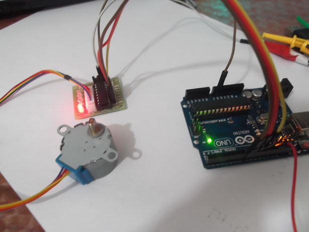
Motor Driver ULN2003 BreakOut Connected To Arduino From IN1 – IN4 To D8 – D11 Respectively
To Power you Motor , Recommanded to use external Power Supply with 5V-500mA at least , Don’t power it directly from arduino Board 5V .
Step 3: Library Direction Issue … And how to fix it .
When You Upload the sketch to the arduino , The Motor will Be rotate in one direction By type the command :
So you must Put the Number of step to turn the motor .
The reference said You can put the positive value to turn one direction, negative to turn the other.
If that’s OK With Your stepper Motor , You don’t need to read the following .
If Not , Your Motor turn to same direction even you Put the steps Positive Value or negative , What is the issue ?
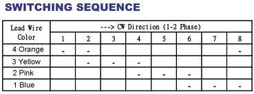
This Motor need to operate as the Table on the attachment .
the arduino Stepper Library need to modify to match this requirement .
I wrote a code which is allow to this motor to Move clockwise and counter clock wise
Code in the next step :
Step 4: Modify Code
the final code for this Stepper motor :
/*
BYJ48 Stepper motor code
Connect :
IN1 >> D8
IN2 >> D9
IN3 >> D10
IN4 >> D11
VCC … 5V Prefer to use external 5V Source
Gnd
written By :Mohannad Rawashdeh
http://www.instructables.com/member/Mohannad+Rawashdeh/
28/9/2013
*/#define IN1 8
#define IN2 9
#define IN3 10
#define IN4 11
int Steps = 0;
boolean Direction = true;// gre
unsigned long last_time;
unsigned long currentMillis ;
int steps_left=4095;
long time;
void setup()
{
Serial.begin(115200);
pinMode(IN1, OUTPUT);
pinMode(IN2, OUTPUT);
pinMode(IN3, OUTPUT);
pinMode(IN4, OUTPUT);
// delay(1000);}
void loop()
{
while(steps_left>0){
currentMillis = micros();
if(currentMillis-last_time>=1000){
stepper(1);
time=time+micros()-last_time;
last_time=micros();
steps_left–;
}
}
Serial.println(time);
Serial.println(“Wait…!”);
delay(2000);
Direction=!Direction;
steps_left=4095;
}void stepper(int xw){
for (int x=0;x<xw;x++){
switch(Steps){
case 0:
digitalWrite(IN1, LOW);
digitalWrite(IN2, LOW);
digitalWrite(IN3, LOW);
digitalWrite(IN4, HIGH);
break;
case 1:
digitalWrite(IN1, LOW);
digitalWrite(IN2, LOW);
digitalWrite(IN3, HIGH);
digitalWrite(IN4, HIGH);
break;
case 2:
digitalWrite(IN1, LOW);
digitalWrite(IN2, LOW);
digitalWrite(IN3, HIGH);
digitalWrite(IN4, LOW);
break;
case 3:
digitalWrite(IN1, LOW);
digitalWrite(IN2, HIGH);
digitalWrite(IN3, HIGH);
digitalWrite(IN4, LOW);
break;
case 4:
digitalWrite(IN1, LOW);
digitalWrite(IN2, HIGH);
digitalWrite(IN3, LOW);
digitalWrite(IN4, LOW);
break;
case 5:
digitalWrite(IN1, HIGH);
digitalWrite(IN2, HIGH);
digitalWrite(IN3, LOW);
digitalWrite(IN4, LOW);
break;
case 6:
digitalWrite(IN1, HIGH);
digitalWrite(IN2, LOW);
digitalWrite(IN3, LOW);
digitalWrite(IN4, LOW);
break;
case 7:
digitalWrite(IN1, HIGH);
digitalWrite(IN2, LOW);
digitalWrite(IN3, LOW);
digitalWrite(IN4, HIGH);
break;
default:
digitalWrite(IN1, LOW);
digitalWrite(IN2, LOW);
digitalWrite(IN3, LOW);
digitalWrite(IN4, LOW);
break;
}
SetDirection();
}
}
void SetDirection(){
if(Direction==1){ Steps++;}
if(Direction==0){ Steps–; }
if(Steps>7){Steps=0;}
if(Steps<0){Steps=7; }
}
